Electrical Submersible Pumps (ESPs) are integral to oil production, especially when natural reservoir pressure is insufficient. However, their failure can halt operations, leading to costly repairs and production losses. This case study examines an ESP failure in the Bakken Shale region, highlighting causes, economic impact, and prevention strategies.
Key Findings:
- Failure Causes:
- Mechanical Issues: Shaft fractures due to material defects and torsional stress.
- Electrical Problems: Overheating from gas locking and fluctuating motor currents.
- Warning Signs:
- Rising motor current (+6 amps over baseline).
- Intake pressure drop (1,650 psi → 1,420 psi).
- Motor temperature nearing alarm thresholds (238°F).
- Economic Impact:
- Production downtime and repair costs.
- Potential recovery of $684,000 annually per 1,000 barrels with predictive analytics.
Recommendations:
- Maintenance: Conduct detailed failure inspections (DIFA) and use predictive analytics to monitor performance.
- Material Upgrades: Use stress-resistant materials and partner with reliable suppliers.
- Operational Practices: Match pump design to well conditions, monitor power quality, and minimize start-stop cycling.
Takeaway: ESP failures often result from a mix of mechanical and electrical stresses. Addressing these through better materials, monitoring, and operational practices can significantly reduce downtime and costs.
ESP Failure Analysis: Warning Signs, Root Causes, and Prevention Strategies
Failure Incident and Operational Context
Well and Operating Conditions
This case focuses on the failure of an ESP in a horizontal well drilled into an unconventional shale formation in the Bakken region. The pump was installed at a measured depth of 8,450 feet, with a true vertical depth of around 7,800 feet. At the pump depth, the reservoir temperature was 215°F, and the bottom-hole flowing pressure was estimated at 1,850 psi when the failure occurred.
The ESP system featured a 250-stage centrifugal pump, powered by a 175 HP motor rated for 2,350 volts and operating at 60 Hz. To address the high gas-oil ratio typical in Bakken wells, a gas separator intake was included. The system’s design targeted a production rate of 1,200 barrels per day of gross liquid, with a discharge pressure of 2,900 psi. The produced fluid had a 42° API gravity, a 35% water cut, and a gas-oil ratio exceeding 1,800 scf/bbl. Sand production averaged 0.3 pounds per barrel, with occasional slugs of higher concentrations during drawdown events.
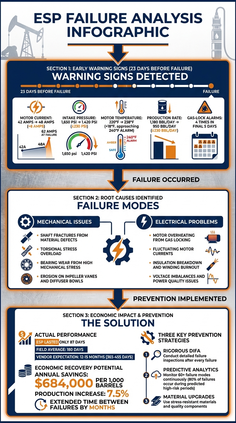
Despite these specifications, the ESP operated for only 87 days before failing – far below the field’s average of 180 days and significantly shorter than the vendor’s expected mean time between failures of 12–15 months for similar setups. The well had already gone through two previous ESP installations: the first lasted 142 days but failed due to motor overheating, while the second ran for 96 days before a bearing seizure necessitated a workover. This history highlighted the well’s challenging environment, which seemed to demand improved equipment or operational adjustments. These conditions laid the groundwork for the early warning signs that would soon emerge.
Early Warning Signs
The harsh operating conditions began to manifest as early warning signs 23 days before the system ultimately failed. Surface monitoring data showed the motor current rising from a baseline of 42 amps to 48 amps, while the intake pressure fell from 1,650 psi to 1,420 psi. At the same time, motor temperature climbed 18°F to 238°F, approaching the 240°F alarm threshold. Production rates also began to decline, dropping from 1,180 barrels per day to 950 barrels per day, even though the variable speed drive frequency remained steady at 58 Hz.
Operators also observed frequent gas-lock alarms, particularly after brief shut-ins for routine well testing. To recover, they reduced the frequency to 52 Hz and allowed the system to stabilize, but these interventions became increasingly necessary in the final week, occurring four times in just five days. On the day of failure, the motor current spiked to 62 amps at 2:15 PM CST, causing the system to trip on overload protection. Restart attempts failed, and subsequent megger testing confirmed zero insulation resistance, indicating motor winding failure.
A review of SCADA data after the failure revealed additional red flags. Discharge pressure had been fluctuating by ±150 psi in the 48 hours leading up to the trip, a strong indicator of gas interference and unstable pump performance. The combination of rising motor current, falling intake pressure, increasing temperature, and erratic discharge pressure suggested the pump was progressively damaged by gas locking, abrasive wear, and thermal stress. Although field personnel were aware of these warning signs, they delayed shutting down the system to maintain production targets and align workovers with operational schedules.
Submersible Pump & Motor Troubleshooting
Root Cause Analysis (RCA) Methodology
After the equipment failure, the operator launched a Root Cause Analysis (RCA) to determine how and why the ESP (Electric Submersible Pump) failed. This in-depth process combined physical teardown, lab testing, and a thorough review of operational data to uncover the root causes. Below, each phase of the investigation is broken down.
Dismantle Inspection and Failure Analysis (DIFA)
The investigation began with a detailed Dismantle Inspection and Failure Analysis (DIFA), a key step in any ESP failure study. Before removing the equipment, field personnel documented the well’s final operating conditions and carefully preserved the motor and pump assembly to retain evidence. Once the ESP was brought to the surface, the team conducted an as‑found visual inspection, recording all components and operational metrics while noting deviations.
During the teardown, inspectors focused on wear patterns, damage points, and failure surfaces. The motor windings showed signs of insulation breakdown, with charring and discoloration consistent with overheating. The pump stages revealed erosion on impeller vanes and diffuser bowls, particularly in the lower stages near the intake, where abrasive solids and gas slugging likely caused uneven wear. The shaft displayed torsional stress marks and minor surface scoring, while the seal section’s bearing surfaces showed heat discoloration and evidence of metal-to-metal contact. Each observation was meticulously documented with photos, measurements, and standardized checklists to ensure accurate reporting. These findings prompted further testing to investigate subsurface issues.
Material and Component Testing
Since visual inspection alone could not detect subsurface defects, critical components were sent to a lab for further testing. Techniques such as chemical analysis, metallography, and hardness testing confirmed that the materials met design specifications, while fractography helped differentiate between fatigue, brittle fractures, and overload failures.
Non-destructive tests, including dye penetrant and magnetic particle inspection, verified the shaft’s structural integrity, ruling out manufacturing defects. The results pointed to operational stresses – rather than material flaws – as the primary cause. The combined effects of thermal stress and torsional loads likely led to the motor’s insulation breakdown and subsequent winding burnout. This reinforced the conclusion that the failure stemmed from operational conditions rather than material deficiencies.
Operating Data Review
While DIFA and lab tests explained what had failed physically, analyzing operating data helped uncover why it happened. Analysts reviewed time-series data from the SCADA system, covering the entire 87-day run. This data included motor current, voltage, frequency, intake and discharge pressures, motor temperature, and production rates. By comparing this data with the physical damage observed during the teardown, the team identified how operating conditions contributed to the failure.
The data revealed a steady rise in motor current, a drop in intake pressure, and repeated gas-lock events leading up to the final overload spike. These trends matched the physical damage patterns identified earlier. Frequent gas-lock events in the final days intensified thermal stress, aligning with the overheating observed in the motor windings. The connection between electrical anomalies and motor damage highlighted the cascading effects of gas locking and insufficient cooling, providing a clear picture of the failure progression.
sbb-itb-325a090
Key Findings and Failure Modes
The investigation pinpointed two main types of failure: mechanical issues arising from material defects and electrical problems caused by challenging operating conditions. Below is a closer look at the mechanical and electrical failures that affected the system.
Mechanical and Material Failures
A major issue involved a critical shaft fracture. Detailed fractography revealed a combination of brittle cleavage and ductile dimples at a weld zone with material defects, indicating torsional overload. Importantly, testing confirmed that the failure was due to poor material quality, not operational overload.
A similar case was documented in South Sumatra, Indonesia. Engineers from Universitas Sriwijaya examined a Monel K500 ESP shaft that failed catastrophically at a depth of approximately 5,085 ft (1,550 m) after less than a week of operation. The shaft had been producing 1,000 barrels per day. Their analysis – using visual inspection, fractography, and finite element modeling – revealed that material defects and weld stress concentrations caused the torsional overload fracture. This failure led to severe equipment damage and significant production losses.
Additionally, bearing surfaces exhibited wear consistent with high mechanical stress levels. While these material issues were a primary factor, electrical stresses further exacerbated the failures.
Electrical and Operating Problems
A review of SCADA data revealed that electrical failures were closely tied to extreme operating conditions. Motor windings showed signs of electrical stress caused by prolonged overheating. Frequent gas-lock events led to fluctuations in motor current and intake pressure, putting additional strain on the system.
Gas interference and frequent start-stop cycles were also identified as contributors to operational instability. Voltage inconsistencies and power imbalances – common in harsh environments like shale formations – further degraded system performance. Predictive analytics have shown that these conditions are linked to 60 different ESP failure modes, with high-risk periods accounting for 80% of failures in test datasets. Ultimately, the combination of electrical stress and mechanical overload exceeded the equipment’s design limits, leading to failure.
Lessons Learned and Recommendations
The analysis of failures highlights key issues such as material defects, electrical stress, and challenging operating conditions. To prevent similar ESP failures, consider these practical strategies and improvements.
Preventive Maintenance Strategies
Drawing from failure analysis, the following maintenance and design practices can help improve ESP performance and reliability.
- Deploy DIFA (Detailed Inspection and Failure Analysis): After each ESP run, document failure modes and component life cycles with photos. This creates a predictive database, turning each failure into a learning opportunity for the entire fleet.
- Use Predictive Analytics for Condition Monitoring: Predictive systems can significantly extend ESP life and boost production. For example, in the Bakken Shale, one analytics solution improved production by 7.5%, extended the time between failures by months, and generated $684,000 in annual savings per 1,000 barrels of energy produced at $25 per barrel. These systems monitor factors like power, pressure, flow, and over 60 potential failure modes to predict issues months in advance and recommend corrective actions.
- Focus on High-Risk Periods: Data shows that 80% of pumps fail during predicted high Risk-of-Failure (RoF) periods. Use this insight to schedule proactive interventions, such as adjusting fluid monitoring or reducing loads, before major damage occurs. Combine this with continuous monitoring of vibration, current, and temperature to detect overload and fatigue early.
Material and Design Improvements
Material quality plays a critical role in ESP reliability. A case in South Sumatra revealed a Monel K500 shaft failure after less than a week of operation due to torsional overload and poor stress resistance. Here’s how to address such issues:
- Upgrade Materials: Use materials with higher resistance to torsional stress and overload. Conduct chemical analyses, microstructure checks, and hardness tests to ensure components meet specifications before installation.
- Partner with Reliable Suppliers: NOVA Petroleum Services and Atokan Drilling Technologies Inc offer high-quality replacement components from leading manufacturers in the USA, Canada, UK, and EU. Their expertise allows operators to source improved shafts, stages, motors, and seals tailored to specific failure histories, backed by over 140 years of oilfield manufacturing experience.
- Improve Weld and Assembly Quality: Stress concentrations at welds can lead to failures. Use advanced methods like finite element stress analysis and fractography to validate designs under real-world conditions. For harsh environments, specify erosion-resistant impellers and corrosion-resistant alloys to combat abrasive fluids and corrosive gases.
These material and design upgrades, combined with disciplined operational practices, significantly reduce the risk of mechanical failures and enhance ESP reliability.
Operating Best Practices
Operational strategies are as important as material and design improvements. Here’s how to optimize ESP performance:
- Match Pump Sizing to Well Conditions: Ensuring the pump’s capacity aligns with production demands is crucial, as illustrated in the South Sumatra case.
- Use Soft-Start Techniques: Minimize inrush currents and mechanical shock by employing soft-start methods or variable speed ramping. This reduces stress caused by frequent cycling.
- Monitor Continuously: Track key metrics like intake and discharge pressure, flow rates, electrical parameters, water cut, solids content, and gas-oil ratio. Even in environments with inconsistent data, predictive models can identify anomalies and reduce downtime.
- Maintain Power Quality: Protect motors and cables by monitoring and correcting voltage imbalances, harmonics, and fluctuations. Monthly reviews of each well’s ESP efficiency against its pump curve and operating envelope can identify and address inefficiencies before hardware damage occurs.
Conclusion and Key Takeaways
ESP failures come with a hefty price – lost production, expensive workovers, and potential equipment damage, not to mention safety risks. This case study highlights that most failures arise from a mix of material defects, electrical stress, and operating practices that push equipment beyond its intended limits. By using structured DIFA (Detailed Failure Analysis) and thorough data evaluation, operators can pinpoint root causes and take steps to prevent future issues.
The economic benefits of proactive management are hard to ignore. For instance, predictive analytics in the Bakken Shale led to a 7.5% production increase and recovered $684,000 annually per 1,000 barrels, primarily by reducing unplanned downtime and extending the time between failures. These numbers clearly show that investing in condition monitoring, disciplined operations, and quality equipment offers returns that far outweigh the initial costs.
Three key practices are essential for improving ESP reliability:
- Conducting rigorous DIFA after every failure to build a knowledge base.
- Continuously monitoring critical parameters like current, pressure, temperature, and vibration to catch early warning signs.
- Staying within operating limits to reduce mechanical and electrical stress.
When these practices are paired with high-quality components and responsive technical support, operators create a reliability program that systematically reduces failure rates across their ESP systems.
Another crucial factor is partnering with trusted equipment suppliers. Companies like NOVA Petroleum Services / Atokan Drilling Technologies Inc provide top-tier pumping systems and components from leading manufacturers in the U.S., Canada, UK, and EU. With over 140 years of oilfield manufacturing expertise, their solutions turn failure analysis into actionable improvements – whether it’s upgrading shaft materials, using corrosion-resistant alloys, or implementing advanced monitoring systems.
At the heart of it all, every ESP failure becomes a chance to learn. By documenting failure modes, operating conditions, and component performance, operators can refine designs, optimize maintenance schedules, and improve field-wide ESP strategies. The insights from this case study – combined with data-driven decisions and strong supplier collaborations – offer a clear path to reducing failures, extending operational life, and maximizing production value across oil and gas operations in the U.S.
FAQs
What are the common early signs of electrical submersible pump (ESP) failure?
If your ESP (Electric Submersible Pump) is acting up, here are some red flags to watch for: unusual vibrations, odd or loud noises, and a noticeable spike in motor temperature. You might also notice irregularities in pressure or flow rates, or the pump cycling on and off more frequently than usual. These could all point to mechanical or electrical problems.
Catching these issues early can save you from more serious damage and expensive downtime. Don’t ignore the warning signs!
How does predictive analytics help prevent ESP failures?
Predictive analytics plays a key role in avoiding failures in electrical submersible pumps (ESPs). By examining performance data, it identifies early warning signs of potential problems. This gives operators the chance to resolve issues before they grow into major disruptions, cutting down on unplanned downtime and expensive repairs.
With the ability to support preventive maintenance and fine-tune pump performance, predictive analytics not only extends the life of ESPs but also boosts operational efficiency. This method helps maintain steady oilfield operations while keeping interruptions to a minimum.
How do material upgrades help prevent failures in electrical submersible pumps (ESPs)?
Upgrading the materials used in ESP components can make a big difference in how well they hold up against everyday challenges like corrosion, erosion, and mechanical fatigue. These improvements help reduce the chances of equipment failure, ensuring the pump performs reliably even under tough operating conditions.
Better materials mean stronger, more resilient parts, which can significantly extend the pump’s operational life. This translates to less downtime and lower maintenance costs. These upgrades are especially important in harsh environments, where standard materials often struggle to handle the wear and tear of extended use.