Gas lift systems help bring oil and gas to the surface when reservoir energy is insufficient. This guide provides a step-by-step checklist to identify and resolve common issues in gas lift operations, covering surface and downhole components. Here’s the quick rundown:
- Safety First: Always follow lockout/tagout procedures, use proper PPE, and monitor for risks like H₂S gas or high pressures.
- Surface Inlet Issues: Check compressors, dehydration units, manifolds, and chokes for proper operation, pressure consistency, and blockages.
- Surface Outlet Problems: Inspect wellheads, valves, flowlines, and separators for leaks, restrictions, or backpressure.
- Downhole Troubleshooting: Confirm injection depth, valve performance, and tubing/packer integrity to ensure efficient fluid lifting.
- Operational Adjustments: Fine-tune gas injection rates and monitor performance regularly to maintain efficiency.
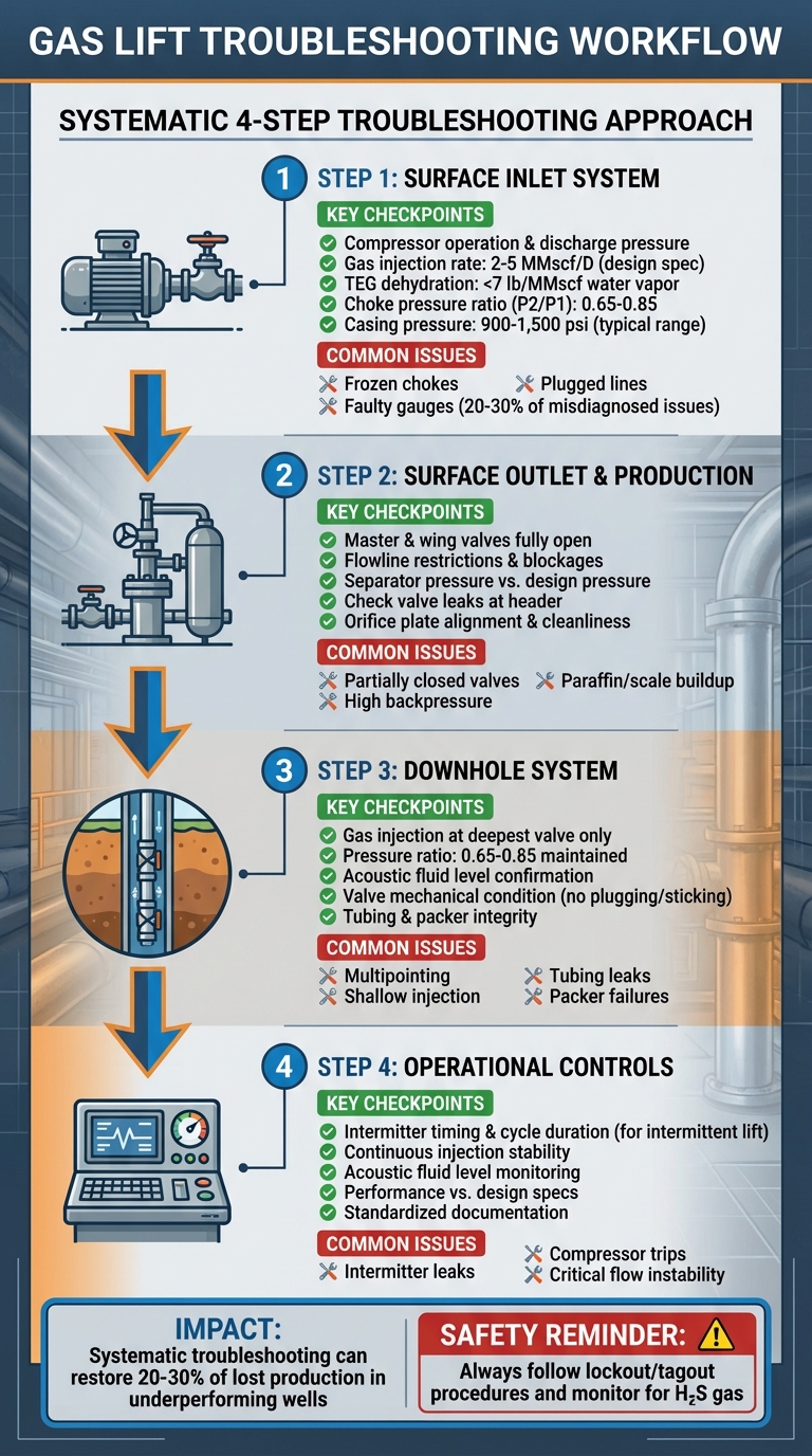
Gas Lift Troubleshooting Workflow: 4-Step Diagnostic Process
2023: Episode 3 – Gas Lift Troubleshooting
Surface Inlet System Checklist
A well-functioning surface inlet system is critical for ensuring gas reaches the downhole system effectively. This system regulates how much gas enters your well and at what pressure. If the surface inlet system fails, even perfectly operating downhole equipment won’t efficiently lift oil. Most issues with surface inlets can be traced to three main areas: the gas supply and compression system, the injection manifold and chokes, and casing pressure measurement.
Gas Supply and Compression
Start by verifying that your compressor is running properly and delivering the correct discharge pressure. Check runtime logs and watch for unusual vibrations or frequent cycling. Repeated compressor failures can prevent wells from reaching steady operation, which limits production.
Use flow meters to measure your injection gas rate and compare it to design specifications – most gas lift wells require 2–5 MMscf/D. If the total demand in the field exceeds the available gas supply, you may notice low casing pressure across multiple wells. Also, inspect scrubbers and knockout drums for liquid carryover, as this can damage compressors and lower their efficiency.
Dehydration units play a vital role. The TEG system must reduce water vapor to below 7 lb/MMscf to avoid hydrate formation. Malfunctioning or heavily fouled TEG dehydrators can allow enough water into the gas stream to form hydrates at chokes and regulators, potentially shutting in individual wells or even entire fields. Check TEG circulation rates, contactor tower temperatures, and filter conditions monthly. If freezing issues or compressor downtime persist, NOVA Petroleum Services offers upgraded compression packages, gas conditioning equipment, and dehydration units from top manufacturers to restore consistent operation.
Injection Manifold and Chokes
Inspect the injection manifold to ensure all valves are fully open and properly aligned. A partially closed isolation valve or an incorrect cross-over setting can starve the well of gas. Measure the pressure upstream and downstream of each injection choke to identify potential restrictions. If the pressure drop is significantly higher than expected, investigate for blockages caused by scale, rust, sand, or paraffin.
Frozen chokes, caused by hydrate formation below 32°F, can reduce injection efficiency by half. If you suspect freezing, inject methanol at 0.5–1 gal/MMscf and review dehydration system performance. For stable flow under critical-flow conditions, maintain a downstream-to-upstream pressure ratio (P2/P1) between 0.65 and 0.85.
Choke sizing is another key factor. An undersized choke restricts injection and leads to low casing pressure, while an oversized choke can allow excessive gas flow, reopening upper valves and causing multipointing. If you find that a choke is incorrectly sized during troubleshooting, replace it instead of trying to adjust valves to compensate.
Casing Pressure and Gauges
Faulty pressure gauges account for 20–30% of misdiagnosed issues. Check the accuracy of gauges by comparing readings at the wellhead, upstream, and downstream of the choke. If available, cross-check these readings with acoustic fluid level measurements. Replace or recalibrate any gauge that shows inconsistent readings or visible damage.
Ensure the casing pressure matches the gas-lift design window, typically 900–1,500 psi for most operations. Low casing pressure can prevent proper unloading to the design depth, while high pressure might indicate an oversized choke or outlet restrictions causing backpressure. During unloading, casing pressure should decline smoothly as injection transitions to deeper valves. Erratic pressure changes may point to multipointing or unstable gas supply.
If casing pressure is unexpectedly low, check for plugged, frozen, or undersized injection chokes. For instance, a plugged choke might reduce pressure from 1,200 psi to 800 psi, halting unloading. On the other hand, high casing pressure with elevated injection volumes often indicates an oversized choke. If high pressure occurs without increased volumes, consider tubing leaks or malfunctioning cut-out valves. Keep detailed records of pressure readings and trends using standardized field forms to aid in ongoing optimization and troubleshooting.
Surface Outlet and Production System Checklist
Once gas reaches the well and flows into the tubing, it continues its journey through the surface outlet system. This system includes the wellhead, flowlines, and separators, and it plays a crucial role in production. However, restrictions along this path can create backpressure, which limits drawdown and reduces output. Troubleshooting guides often highlight that addressing surface restrictions is one of the quickest ways to boost production before considering changes to downhole equipment. Start by ensuring the wellhead components are free of leaks and blockages.
Wellhead and Valves
Begin by checking that the master and wing valves are fully open. Partially closed valves are a known cause of outlet issues in gas-lift wells. Visually confirm valve positions and inspect for leaks, packing failures, or corrosion around valve bodies and flanges. Measure pressure both upstream and downstream of key outlet valves to identify unusual drops, which could signal internal restrictions or debris. If a valve appears to be causing a restriction, systematically crack and re-seat it while monitoring pressure changes. Additionally, inspect check valves at the header, as leaking check valves can add unnecessary backpressure. Replace any problematic valves rather than compensating with downhole adjustments. Once valve functionality is confirmed, move on to the flowline and choke system.
Flowline and Choke Inspections
Examine the entire flowline from the wellhead to the separator for any areas with reduced internal diameter, such as temporary spool pieces or outdated choke bodies. If possible, remove the choke body (not just the bean) from the flowline, as it can contribute to backpressure. For cases where a choke is necessary – whether for rate control or erosion protection – ensure the choke bean size matches the well design and production goals. Beans that are too small can cause excessive backpressure, while oversized beans may lead to unstable flow and slugging.[2,3]
Address any backpressure caused by the flowline immediately. Look for signs of paraffin, scale, or hydrate buildup, which might show up as temperature drops, pressure increases, or slugging behavior. Reviewing chemical treatment records and conducting spot pressure surveys at accessible locations can help identify partial blockages or internal corrosion. If the flowline is shared by multiple wells, confirm that the combined line capacity isn’t exceeding hydraulic limits.
Separator and Measurement Systems
Next, evaluate the separator and measurement systems for potential backpressure sources. High separator pressure is a common sign of outlet restrictions. Compare the actual operating pressure of the separator to its design or target pressure, and check that pressure controllers and control valves are functioning correctly. High separator pressure can decrease gas-lift efficiency, so lowering it – while staying within facility limits – can enhance well performance.
Inspect the orifice plate or meter to ensure proper sizing and cleanliness, as misaligned or dirty plates can restrict flow or lead to inaccurate rate measurements. Confirm that level controls, dump valves, and relief systems are functioning as they should. Also, verify that all measurement instruments, including those for pressure, temperature, and flow rates, are properly calibrated. This ensures accurate diagnosis of whether backpressure originates at the separator or further upstream.[3,5]
If surface outlet restrictions – like persistent choke erosion, hydrate plugs, or undersized components – continue to hinder production despite basic troubleshooting, it may be time to consult specialists. NOVA Petroleum Services can assess surface layouts, verify the sizing and selection of valves, chokes, meters, and separator components, and suggest updates or replacements tailored to U.S. operating conditions. This includes recommending materials suitable for corrosive or high-CO₂ environments.[2,3,5]
sbb-itb-325a090
Downhole System and Valve Performance Checklist
Once you’ve confirmed that the surface outlet is running efficiently, it’s time to shift attention to the downhole components. These include valves, mandrels, tubing, and packers, all of which need to perform seamlessly at the target depths to lift fluids effectively. Failures in these areas can quietly cut into production without showing clear signs at the surface. To troubleshoot downhole issues, carefully observe pressure behavior, injection depth, and valve responses to identify where the system might be faltering. A thorough check of injection depth accuracy and valve functionality is crucial for completing the assessment.
Injection Depth and Unloading Behavior
Gas injection should occur exclusively at the deepest valve. If the gas is injected too shallow (a condition known as multipointing), it prevents full unloading, leaving excess fluid in the tubing and reducing drawdown efficiency. During unloading, monitor casing pressure downstream of the injection choke. A controlled pressure decline, as the system shifts from shallower to deeper valves, indicates proper unloading. Acoustic fluid level tools in the casing annulus can help confirm the actual injection depth and ensure the fluid level is dropping as expected.
If the well doesn’t fully unload, consider redesigning the valve spacing or replacing dummy valves with active gas lift valves to allow deeper injection. Maintaining optimal pressure ratios – typically between 0.65 and 0.85 – is essential to avoid critical flow conditions that could disrupt valve performance and unloading stability.
Once injection depths are verified, assess the mechanical performance of valves and mandrels to confirm they are responding correctly to downhole pressures.
Gas Lift Valves and Mandrels
Gas lift valves need to be inspected for mechanical problems or contamination that could interfere with their ability to open, close, or meter gas properly. Common issues include plugging from salt or debris, valves sticking open or closed, or incorrect pressure settings. Signs of valve trouble include fluid levels standing at or above the bottom valve, excessive backpressure reopening upper valves, or unstable injection rates despite a steady surface gas supply.
Pressure surveys can help locate the gas entry point. Persistent high casing pressure without a decline often signals shallow injection, while high injection volumes reopening upper valves indicate multipointing. Wireline valve checks or echo meters can verify valve depth and condition. During workovers, clean the casing with scrapers and use filtered fluids to minimize debris that could damage or clog valves over time. Replace any valves showing leaks, incorrect settings, or damage rather than relying solely on surface adjustments.
Tubing, Packers, and Leaks
Tubing leaks, packer failures, or restrictions can significantly reduce system performance. Tubing leaks or damaged valves often present as low casing pressure despite sufficient gas supply, difficulty unloading, or erratic production. Packer failures, on the other hand, allow unwanted communication between the annulus and tubing, disrupting injection profiles and preventing gas from reaching its intended depth. Investigate "no feed-in" conditions – where fluid stands at or below the bottom valve – for potential causes like covered perforations, packer issues, or valve spacing that is too wide for proper unloading.
Inspect tubing for issues like scale, paraffin buildup, or collapse, and plan for mechanical or chemical cleanouts as needed. Verify packer integrity, paying close attention to leaking pack-off gas lift valves that can bypass gas and disturb the injection profile. For persistent problems such as repeated multipointing, chronic valve failures, or complex dual gas lift setups, NOVA Petroleum Services offers expertise in reviewing downhole valve and mandrel designs. They can recommend upgraded valve types or materials tailored to U.S. operating conditions (psig, °F, ft TVD) and provide support for equipment renewal or replacement to align with your production goals.
Operational Controls, Diagnostics, and Documentation Checklist
Once downhole checks are complete, shift your attention to operational controls to fine-tune gas injection and system performance. Whether you’re working with intermittent or continuous gas lift systems, proper adjustments can minimize gas waste and stabilize production. Keep detailed records of observations and adjustments to streamline troubleshooting in the future. While surface and downhole components may already be verified, maintaining operational controls and consistent diagnostics is key to ensuring long-term reliability. The next step? Reviewing gas lift control modes to confirm that each system is running efficiently.
Intermittent and Continuous Gas Lift Controls
For intermittent gas lift, ensure the intermitter is functioning correctly – whether it’s battery-operated or a manual wind-up. Check that it hasn’t stopped unexpectedly. Verify the cycle timing and fine-tune the injection duration to maximize fluid recovery while minimizing tail gas losses. If you notice casing pressure increasing between cycles, it could indicate an intermitter leak; inspect and replace the seat or seals as needed. Avoid choking the intermitter itself, as this can disrupt the timing and harm efficiency.
For continuous gas lift wells, focus on maintaining steady injection pressure and consistent flow from compressors and regulators. Frequent compressor trips, hydrate formation, or liquid accumulation in poorly dehydrated gas can hinder operations, leaving wells stuck in start-up mode. To avoid pressure interference and instability, separate intermittent and continuous gas lift wells onto distinct supply systems. Additionally, keep the injection choke pressure ratio (downstream pressure divided by upstream pressure, P₂/P₁) below 0.60. Operating in the 0.65–0.85 range can lead to critical flow conditions, destabilizing the injection process.
Performance Monitoring and Diagnostics
Monitor performance by comparing current readings to the system’s design specifications. Use acoustic fluid level tools regularly to confirm injection depth and ensure unloading progresses to the intended operating valve. Any discrepancies could indicate shallow injection or blocked deeper valves. During unloading, track casing pressure drops and correlate them with deeper valves taking injection – this common field practice can uncover issues like multipointing or unloading failures. Additionally, test separator data or multiphase meters can help calculate well performance metrics, flagging underperforming wells for immediate troubleshooting.
Field Documentation and Standardized Forms
Effective monitoring must go hand-in-hand with standardized documentation to capture critical system data. Use standardized troubleshooting forms to categorize inlet, outlet, and downhole issues clearly. Record pre- and post-action data, such as pressures, rates, intermitter settings, timestamps, and the technician responsible, to facilitate future reviews and cross-well comparisons. Adopt consistent terminology and codes for recurring problems (e.g., shallow injection, multipointing, high backpressure) to ensure uniform analysis across multiple wells. When it’s time to upgrade or replace components – like older intermitters, gas lift valves, or surface controls – NOVA Petroleum Services offers reliable solutions tailored to U.S. operating standards (psig, °F, ft TVD). Their components and support can help keep your artificial lift systems optimized and well-documented for sustained performance.
Conclusion
From surface inlets to downhole controls, each chapter of the checklist lays the foundation for smoother, more efficient operations. A well-structured troubleshooting checklist transforms reactive problem-solving into a proactive strategy. By systematically addressing surface inlet systems, outlet and production equipment, downhole components, and operational controls, you can pinpoint the root causes of issues – whether it’s a clogged choke, a leaking valve, or incorrect intermitter settings. This method eliminates days of trial-and-error downtime and can restore 20–30% of lost production in underperforming wells through precise, targeted solutions. Beyond fixing current problems, it creates a reliable guide for future troubleshooting efforts.
Standardized documentation enhances these outcomes even further. By recording key details like pressures, temperatures, injection depths, and corrective actions, you build a comprehensive knowledge base for your field. When similar issues appear across multiple wells, this organized data can significantly simplify and speed up the troubleshooting process.
Once immediate problems are addressed, the focus should shift to ensuring long-term reliability. Reliable equipment plays a critical role here. After handling quick fixes, consider upgrading outdated components – swap out dummy valves for properly spaced gas lift valves, invest in high-reliability compressors, and modernize control systems. Routine maintenance, such as casing scraping and using filtered fluids, can also help prevent common issues like valve plugging before they disrupt production.
Consistent performance across all checklist areas depends on using quality components and having dependable support. NOVA Petroleum Services offers high-quality gas lift components and artificial lift systems designed to meet U.S. standards. Their services include equipment renewal, replacement, and upgrades, ensuring your systems remain efficient and reliable. Whether you’re in need of valves, mandrels, compressors, or dehydrators, partnering with a trusted supplier makes it easier to transition from troubleshooting to sustained, optimized operations.
FAQs
What are the main reasons gas lift systems fail?
Gas lift systems can run into trouble for several reasons, with some of the most frequent culprits being poor installation practices, corrosion, or blockages in the tubing or valves. Additionally, issues like inadequate pressure or flow rates and wear-and-tear on essential components often lead to failures.
Staying on top of regular maintenance and conducting routine inspections is crucial. These proactive steps can catch problems early, keeping the system running efficiently and minimizing downtime.
How do I make sure my gas lift system provides accurate pressure readings?
To keep your gas lift system delivering precise pressure readings, make it a point to calibrate your pressure gauges regularly. This step ensures the accuracy you need for smooth operations. Choose durable, high-performance pressure sensors that can handle the tough conditions of oilfields – this helps reduce errors caused by external factors like temperature changes or harsh environments.
On top of that, stick to a routine schedule for inspections and maintenance. This way, you can catch and fix issues like sensor drift, malfunctions, or physical damage before they escalate. A well-maintained system not only boosts reliability but also keeps everything running efficiently.
What should I do if I suspect hydrate formation in my gas lift system?
If you think hydrates are forming in your gas lift system, here’s how you can tackle the problem:
- Shut in the well if needed to stop the situation from worsening.
- Use heat – methods like heat tracing or circulating hot water can help dissolve the hydrates.
- Lower the system pressure to create conditions less favorable for hydrate formation.
- Inject hydrate inhibitors such as methanol or glycol to break down existing hydrates and keep new ones from forming.
- Inspect and clean the system to remove any hydrate plugs that might be blocking the flow.
- Take preventive steps like installing chemical injection systems to reduce the risk of future issues.
Keeping an eye on the system and making timely adjustments is crucial for smooth operations. For professional guidance or access to specialized tools, consider contacting NOVA Petroleum Services.